FINAL PROJECT – BIM USING REVIT
DYNAMO
The
final project focuses on methods to implement visual programming using Revit
Dynamo. The parametric models created in Project 1 are visually enhanced using
Dynamo, another feature offered by Revit. In this project, I have primarily
focused on three main portions:
- · Solar Coloring of external façade driven by sun path
- · Panel Surface Coloring
- · Making instance parameters of curtain panels to be driven by sun path
SOLAR COLORING OF EXTERNAL FAÇADE
In
this part of the project, I have tried to change the color of the external façade
pattern based on sun path. Dynamo is used to get the current sun settings and
then make the color of the external curtain wall pattern to be driven by it.
The
first step was to read the curtain panels from the Revit project into the
dynamo program. To achieve this, node “family types” is introduced in the
program which reads the curtain wall pattern. Three curtain panels are read
using this node. Curtain Panel 1 exterior, curtain panel 2 and curtain panel 3
created in first project are read into dynamo.
The
Solar Coloring for the above three mentioned follows similar procedure in
Dynamo. However, the Dynamo program is split into two parts. The first part
considers the solar coloring of curtain panel 1 exterior and the second
considers the solar coloring of curtain panel 2 and curtain panel 3. The main
reason behind this was to make the solar coloring of panels 2 and 3 to be
always yellow in color, irrespective of the time of the day. This effect was
considered primarily due to the existence of the torch, which is considered to
radiate a yellow lighting effect on these panels. The dynamo coding for these
two parts is very similar with the only change being that the time span for
panels 2 and 3 is increased by 9 hours to account for the time difference and the
time is checked in dynamo to ensure that yellow coloring is achieved. This part
is illustrated in the figure below. The code tends to add 9 hours to the
current time and then checks whether the current time is within the time
indicated from the Dynamo code. Once this is checked, color for these panels is
assigned by using the “Color by ARGB” node to the panels 2 and 3.

Figure 1: Time adjustment and checking for time
Assigning colors (general process for
panels 1, 2 and 3)
1.
The first step is to read all the curtain panel elements by using the “Family
Types” and “All Elements of Family Type” node.

Figure 2: Reading the family types and creation of
surfaces
2.
This is followed by the creation of surfaces and finding the normal to the
surface by using the “Surface. Normal at parameter” node. 0.5 assigned to this
node considers the center point of the surface.

Figure 3: Finding surface normal and vector dot
product
3.
Next step, is to get the Sun Settings and then calculate the vector dot product
between the sun direction and the surface normal. Figure 3 also illustrates the
use of Remap Range to get these values of dot products into the range of 0 to
1. This is because to facilitate the input for the “Color Range” node which
only accepts values between 0 to 1
4.
The next step is to use these remapped values and assign colors to the
respective family types. “Color by ARGB” is used to get the color range and
then “Element Override color in view” can be used to overwrite the element
color.
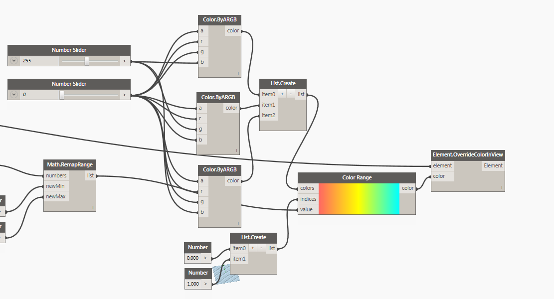
Figure 4: Overwriting family type colors depending on
sun path.
The creation of solar
coloring panels for 2 and 3 also follows the similar procedure with the only
change being that the curtain panels are read into a list. This list is then
used to generate surfaces. The steps following this remains the same as
outlined above.

Figure 5: Creation of list for panels 2 and 3 followed
by subsequent coloring
The whole dynamo code for
the panels 2 and 3 coloring are s shown below.

Figure 6: Whole dynamo code for panels 2 and 3
coloring

VISUAL RESULTS
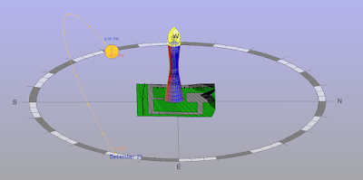
After execution of the dynamo code, the output visual results obtained were as follows. First figure shows the solar coloring at 8 PM and the second shows the solar coloring at 2:45 PM.

Result 1: Panel Coloring at 8 PM

Result 2: Panel Coloring at 2:45 PM
PANEL SURFACE COLORING
This
part of the project focuses on assigning random colors to the surfaces of curtain
panels 1 exterior, 2 and 3. Thus, this part required modification of the
curtain pattern families for 1,2 and 3 in order to facilitate this. To achieve
this, four different materials were created and then the number of panels of
each family type was calculated from Dynamo. Once this was accomplished, random
values were generated in spreadsheet by using “Randbetween” formula. Once, this
was accomplished a Python script was run to read the numbers from the excel
file and link the number to the material number and assign the material to the
panel. The process is sequentially as explained below.
Modification
of curtain Panels
The
curtain panels created in project 1 were then modified to add surfaces. These
were then overwritten at the family level to incorporate the modification in
the design. These are as explained below.
Modification of curtain panel 1
exterior
The
modification comprised of adding a surface to the curtain panel created in
Project 1 whose color would then be overwritten by using Dynamo, thereby
incorporating visual effects. The modification is as shown in the figure below.

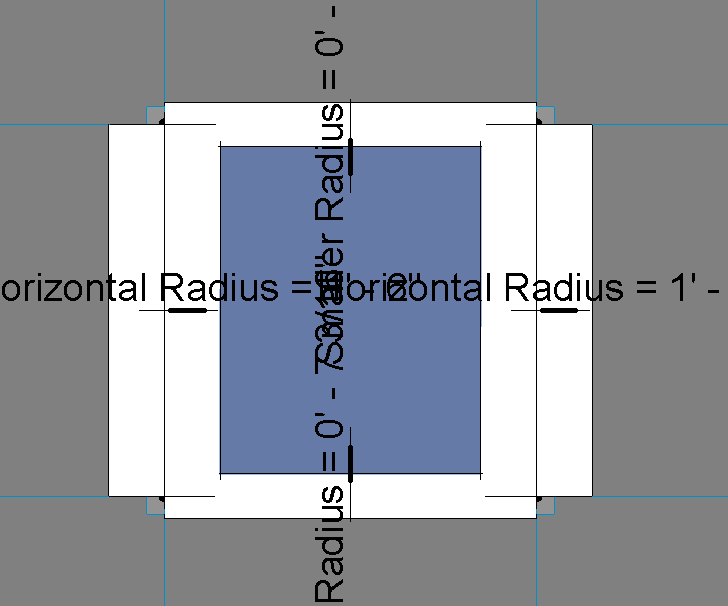
Figure 7: Blue surface depicts the surface added to
the pattern
The
material for this surface is then linked to a shared parameter which is
available across multiple family files. Once this shared parameter is linked,
the material can be overwritten at the project level.

Figure 8: Association between instance and Shared
Parameter
This same process is then
repeated for panels 2 and 3.


Figure 9: Modification of curtain panels 2 and 3
Creation of Materials
The
next step was to create different materials type which will override the
element color. I have chosen to create 4 different material types which will be
used to overwrite the panel surface colors. To achieve this in the Materials
Property dialog box, I created 4 different materials, Myglass1, Myglass2, Myglass3
and Myglass4.

Figure 10: Creation of different materials for Panel 1
Coloring
For
coloring panels 2 and 3, I again created two more materials Myglass5 and
Myglass6 which were used to overwrite the panel surface coloring.
Creation and Linking materials in Family
This
was followed by the creation of four material parameters in the family project
file which were then linked to the materials created above. For this purpose, I
carried out the Panel 1 overwriting process in a separate family and panels 2
and 3 in a separate family. Once, I finished modifying the Panel colors for
panels 2 and 3, I then overwrote the already existing family file in this
environment with the previous one. This was because my top portion was modeled
separately in Revit family file and my bottom portion was a different Revit
family file.

Figure 11: Family parameters created for panel 1
surface coloring

Figure 12: Family parameters created for panels 2 and
3 coloring
Modification of the Panel Surface Colors
The
next step was to modify the colors of the panels 2 and 3 overwritten at the
family level. The Panel Surface Colors is split into two parts. Panel 1
overwriting is performed separately and Panels 2 and 3 are done separately. But
the concept used and the Python script generated is the same. The first step
common to both the parts was to identify the number of panels of that family
type. This was achieved by using the “List. Transpose” node. Once the number of
panels were calculated, Excel software was used to generate random numbers from
0 to (number of materials-1) using the “Randbetween” command. The formulas used
can be seen in the pictures shown below. The number of cell values are the same
compared to the number of curtain panel instances in the Revit file.

Figure 13: Excel file to generate random numbers for
Panel 1 (0 to 3)

Figure 14: Excel file to generate random values for
panels 2 and 3 (0 to 1)
Dynamo Flow
Once
the steps outlined above are completed, dynamo is used to access all the files
already created. The steps include:
1.
Reading all the elements from the desired family type. In this case, it is
Panel 1. Similar procedure is followed for Panels 2 and 3

Figure 15: Creation of Family Types
The
other important thing is to notice the “Element. SetParameterByName” node which
overwrites the material for the assigned panel surfaces.
2.
Reading data from the excel files created above. For this purpose, the “Excel.
Readfromfile” node is used.

Figure 16: Reading data from Excel files generated
3. Creating list based on
the number of materials assigned to the Panel Color.

Figure 17: List Creation with different materials
4.
Generating the Python Script that reads the value stored in each index and
associates the material number with that index number. Here, I have used only
one temporary variable “val” which is used for both reading and assigning
materials based on the index number. This tends to save computer storage and
computational performance. The python script is as shown below. Once this
script runs, the next step is to link the output of this script to the input of
Set Parameter by name node to overwrite the colors. The results of this can
been seen in the later part of the blog.
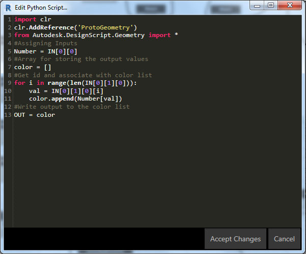
Figure 18: Python Script
These processes combined
together are represented in the picture below. With this, the Panel Surface
coloring of Panel 1 is completed.

Figure 19: Whole Dynamo code for Panel Surface
Coloring – 1
Similar procedure as
outlined below, is used for the second part. The only difference is the
creation of list to read both family types at the beginning of the code.

Figure 20: Whole Dynamo code for Panel Surface Coloring
2 and 3
VISUAL RESULTS
The Panel surface coloring for curtain panel 1 exterior is as shown below.

Result 3: Panel Coloring for Curtain Panel - 1
The panel surface coloring for the top portion of the model is as shown in the figure below. The panel surface coloring for this portion is done on a separate family file.

Result 4: Panel Surface Coloring for Curtain Panels 2 and 3
Once the panel surface coloring for the top portion is completed, the top portion is then overwritten in the project file to complete the panel surface coloring for the whole structure. The completed project file is as shown in the picture below.

Result 5: Final Panel Surface Coloring of the whole structure
Another view of the completed project file is shown below.

Result 6: Another view of the final Panel Surface Coloring
In
this part of the project, I have tried to control the instance parameters of
the curtain panel 1 to be driven by the sun path. The parameter “Extrusion” is
driven by the sun path which also changes colors depending on the orientation
of the curtain panel with the sun direction. In short, the thickness and the
color of the curtain panel is driven by the sun path. The main motivation and
the idea behind this was obtained from the last lecture class of Dr. Wei Yan,
Architecture 653 course at Texas A&M University. The process flow is similar
to the one taught by Dr. Yan in class and thus I felt that this was much
related to my model. So, I decided to implement this for my project with minor
modifications to suit my model.
Modification of the Curtain Panel
This
part of the project also involved modifying the curtain panel 1 pattern from
Project 1. The curtain panel is modified to be a simple rectangular surface
with an extrusion. This extrusion height is controlled depending on the sun
direction.
The
design of the curtain panel is as shown below.

Figure 21: Curtain Panel modification
Creation
of a family parameter “Extrusion” that is available in the subsequent project
files for modification.

Figure 22: Creation of family parameter Extrusion
This curtain panel is
then loaded and overwritten in the new project file.
Creation of Divided Surfaces
The
next step was to create divided surface from the Revit model which can then be
used to get the locations of the adaptive components. For this purpose I used
the “Adaptive Component. Locations” node. The results of this were then written
to an excel file using the “Excel.Write to file” node. This part considers two
separate divided surface families due to the massiveness of the model. The
Dynamo code for this process is as shown below.
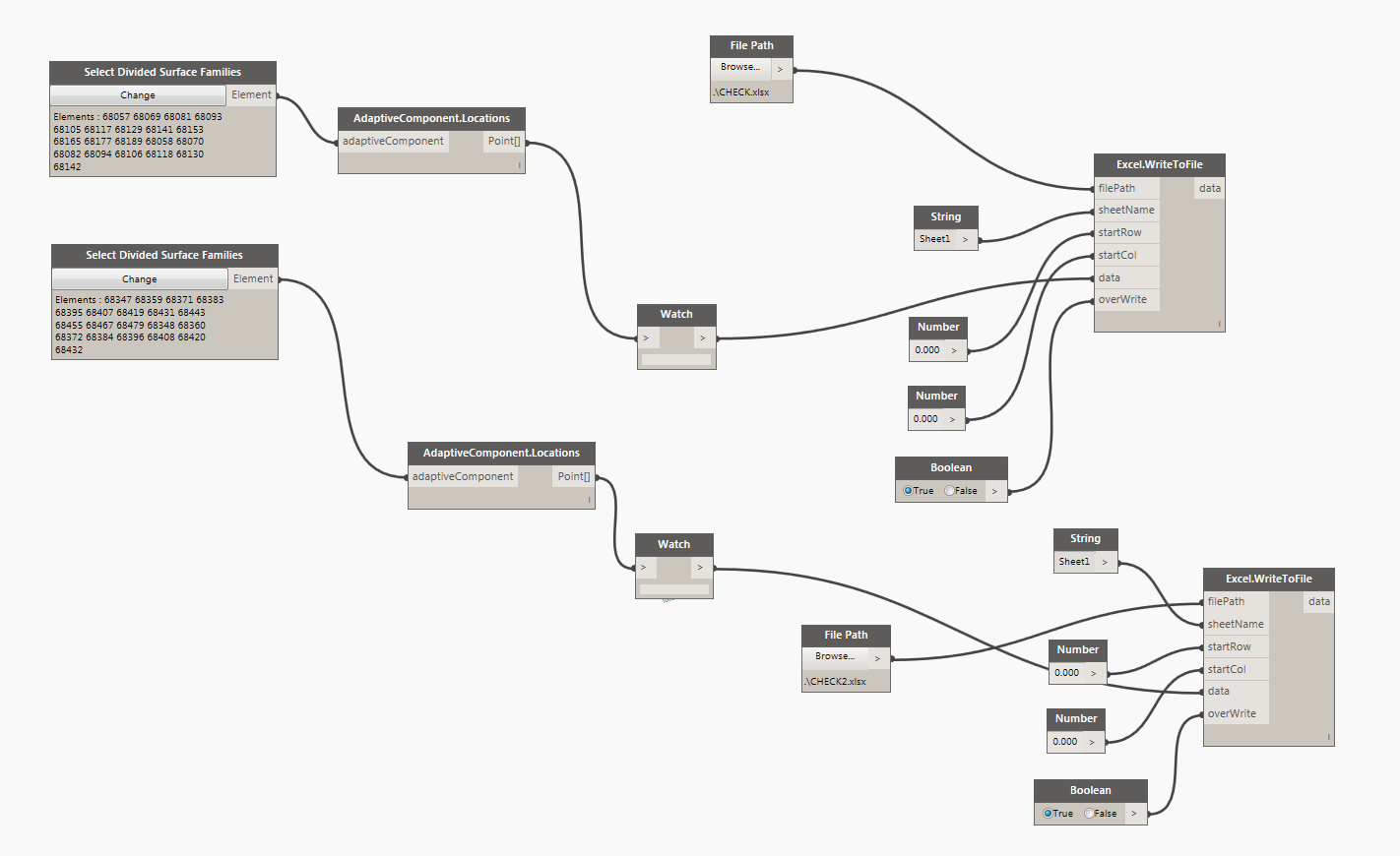
Figure 23: Dynamo Code to get adaptive component
locations and writing to excel file
Modifying instance parameters to be driven by sun path
The
Dynamo code consists of two parts for the two divided surface families.
Essentially, the same flow path is generated for both the families. Thus, the
sequence of Dynamo code flow is as shown below.
1.
Reading from the excel file already created in the previous step to get the locations
of the Adaptive Components.

Figure 24: Reading from the excel file
2.
Creation of Polygon Surfaces and the Adaptive Components. This is accomplished
from the Dynamo Code shown below.
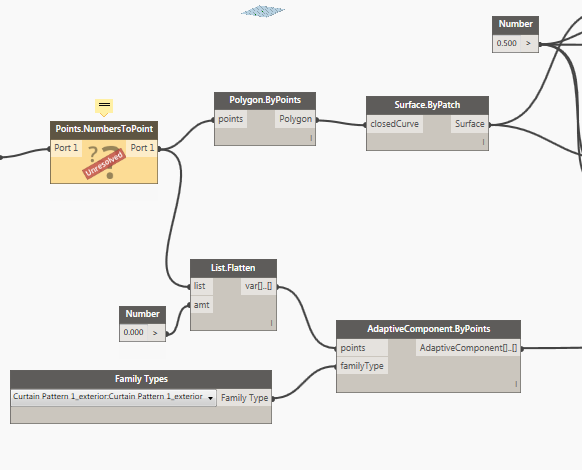
Figure 25: Creation of Polygon and adaptive Components
Note: Yellow node signals error which can be eliminated by downloading "Lunchbox for Dynamo" package.
3.
Finding out the surface normal and representing the normal with a vector using “Line
by Start Point End Point” node.

Figure 26: Finding out the Surface Normal
4. Finding out the angle
between the Sun direction and the Normal to the Surfaces by using the “Vector.
Dot” node

Figure 27: Finding out the angles between normal and
sun direction
5.
Remapping the values of the Dot product and changing the color of the panels
based on the values of the dot products. For remapping the values. “Math. RemapRange”
node has been used and for the overriding of colors “Color By ARGB” node has
been used.

Figure 28: Overriding Color for the panels
6.
Using Control parameter “Extrusion” to define the instance parameters of the panel
to be driven by sun path. For this purpose “Element.Setparameterbyname” node
has been used. This completes the visual design of the panel surfaces.

Figure 29: Controlling Instance parameter “Extrusion”
based on the sun path
The
same code is repeated for the other divided surface family to finish modelling
and controlling the behavior of the instance parameters based on sun path.
VISUAL RESULTS
The divided surface for curtain panel 1 was obtained from this project file. The project file gives the locations of the adaptive components or points, which are then written to an excel file. The excel file is revised so as to just get the coordinates of the points and to remove other data which can possibly be flagged as errors by Dynamo. The excel file is then converted into a string file.

Result 7: Revit family file used to get locations of the Adaptive components (writing to excel)
The Panel surface coloring at 12 PM is shown below.

Result 8: Panel Coloring for 12 PM
The Panel surface coloring at 7 PM is shown below.

Result 9: Panel Coloring for 7 PM
Variation in the Instance Parameter values based on orientation with the sun
It can be observed that the panels facing the sun have thinner panels. In other words, the panels facing the sun have small values of extrusion. This is explained in the figure given below.

Result 10: Smaller values of extrusion for panels facing the sun (Panel indicated by blue color)
It can also be observed that the panels away from the sun have greater values of thickness. This is shown in the figure given below.

Result 11: Greater values of extrusion for panels away from sun (Panel indicated by blue color)
The increase in thickness of panels relative to each other is shown in the figure given below.

Result 12: Change in panel thickness depicted clearly
PROJECT VIDEO
CONCLUSION
Thus, Dynamo was used to add good quality visual representation to the Aspire Tower model. Several different types of visual lighting features were explored with Dynamo. Visual Representation under solar path and varying instance parameters of some families to be driven by sun path all point to the diversity that is offered by this software.
It can also be said that Dynamo offers several other features too which can be used to improve and enhance visual quality of models created. However due to time constraints, some of the tougher visual quality representation were not dealt with. Through this project, I was also able to understand the importance of adding good visual quality to the models that I created.
ACKNOWLEDGEMENTS
I would like to thank Dr. Wei Yan for constant support and encouragement throughout the ARCH 653 course. His patience and enthusiasm in clearing doubts and good quality lectures is highly appreciated.
REFERENCES
1. Autodesk website - https://academy.autodesk.com/curriculum/bim-advanced-computational-design
2. Arch 653 Lecture 23 by Dr. Wei Yan - http://bim-sim.org/ARCH653/lectures/lecture23/1.html
3. Google
4. Students Gallery tab at ARCH 653 website
No comments:
Post a Comment